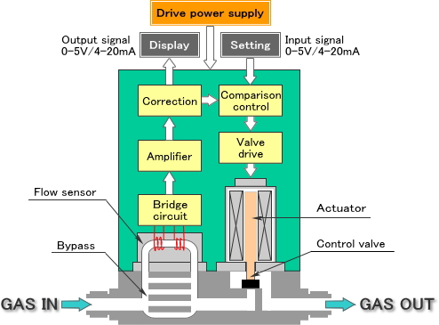
mass flow controller symbol
Whisper MCWSeries Low Pressure Drop Mass Flow Controllers. In addition to the flow meters for flow monitoring applications flow regulators and controllers are equipped with an in-built needle.

Bliznjice Zahodni Ti Si Flow Meter Symbol Marchgourdmadness Com
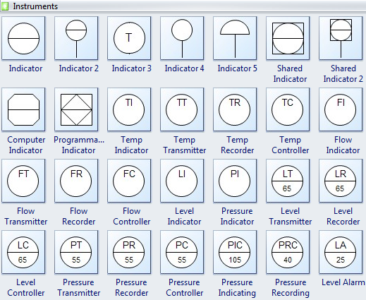
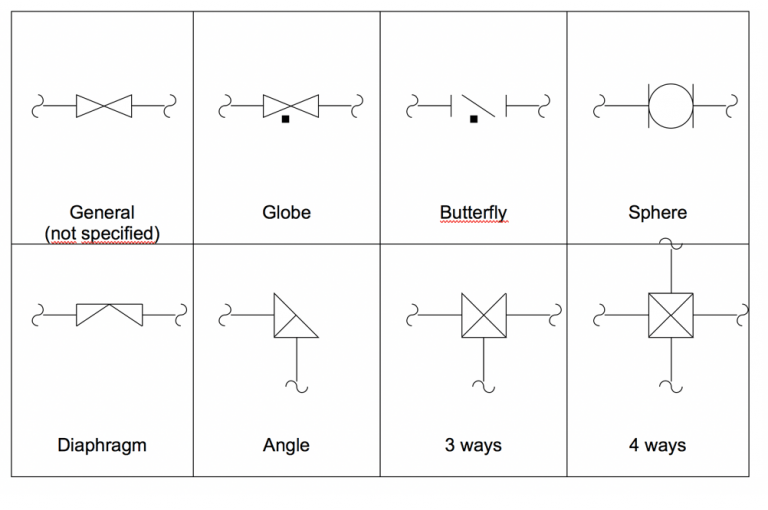
The symbols used in piping and Instrumentation diagrams or drawings are many and varied.

. Piping and Instrument Diagram Standard Symbols Detailed Documentation provides a standard set of shapes symbols for documenting PID and PFD including standard shapes of. We can determine the value of the mass flow rate from the flow conditions. Digital Mass Flow Controller Model F4Q The model F4Q is a high-performance mass flow controller with high-speed responselow puressure loss and high accuracy.
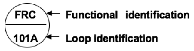
In the case of the same tag numbers the process pressure correcting element usually a control valve often has the same tag number as the controller. The Mass Flow Controller Market produces mass flow controllers for use in certain industries. The Mass Flow Controllers are very complex machines that work with a combination of sensors and.
I have dealt with some of these symbols before but here I have given a comprehensive list of the common PID symbols of process equipment such as valves flowmeters piping line connections and much more. The conservation of mass continuity tells us that the mass flow rate through a tube is a constant. Mass Flow Device Safety Information Symbols Used in This Instruction Manual Definitions of WARNING CAUTION and NOTE messages used throughout the manual.
MultiFlo technology allows one device to change gas types and ranges without removing the device from the system and improving actual process gas accuracy. It senses records and controls various process parameters to achieve best product quality at maximum economy and safety. The MASS-VIEW flow meter series incorporates a digital bar graph of actual gas flow which is thanks to the OLED organic light emitting diode technology clearly visible from all angles as well as indicating flow units gas type and totalised figures.
Definition of Symbols Found on the Unit On Supply IEC 417 No5007 Off Supply IEC 417 No5008 Earth ground IEC 417 No5017 Protective earth ground IEC 417 No5019 Frame or chassis. Instrumentation is a brain behind process control. Symbols Found on the Unit Mass Flow Controller Safety Information 2 Symbols Found on the Unit The following table describes symbols that may be found on the unit.
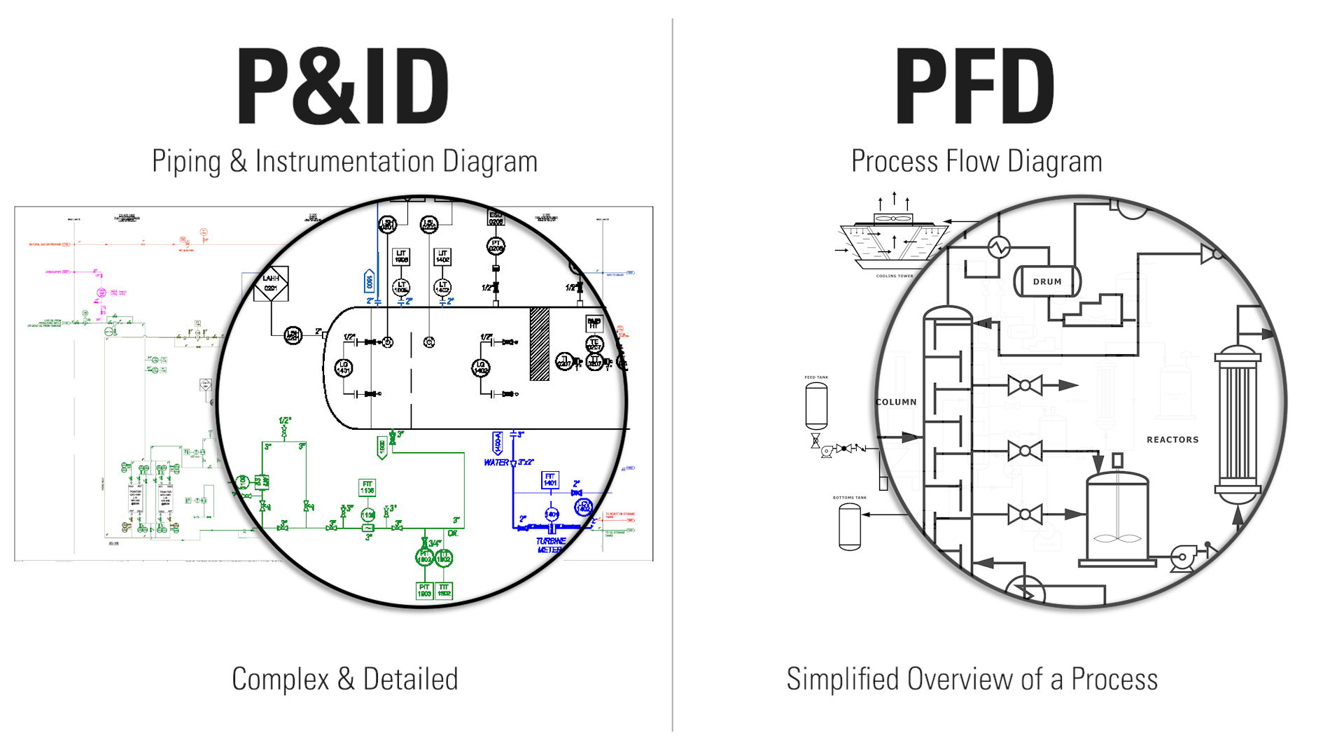
Guideline for Pressure Specifications of the Mass Flow Controller. The Process flow diagrams are used to understand the process and its sequence model a process document a process ensure quality control. The volume v is.
Standard for Mass Flow Controller and Mass Flow Meter Linearity 10 SEMI E28-00-0092. MultiFlo is offered for use with thermal thermal mass or flow sensors. Access to device functions Allowing you to adapt the controller behavior and various settings.
Here is a list of PID symbols pertaining to Instrumentation. Rapidly reach setpoints to maintain stable control of mass flow volumetric flow or pressure for 98 gases from 001 to 100 of full scale. Warning The WARNING sign denotes a hazard.
Industry-best range of digital mass flow meters and other products to meet widest application needs. Mass Flow Controller Safety Information 1 Mass Flow Controller Safety Information Symbols Used in This Instruction Manual Definitions of WARNING CAUTION and NOTE messages used throughout the manual. Flow Nozzle Meter symbol.
Guideline for Pressure Specifications of the Mass Flow Controller 11 SEMI E56-00-1296. For example a pressure indicating controller installed in a process unit coded 11 and identified by serial number 1101 is described in written form as 11 PIC 1101. The MKS Type 1150C Mass Flow Controller MFC is designed for precise and repeatable mass flow control of most low vapor pressure liquid or solid source materials into low pressure processes such as Low Pressure Chemical Vapor Deposition LPCVD Metal Organic Molecular Beam Epitaxy MOMBE and others.
Control flow when there is little available system pressure with pressure drops as low as 007 PSID 48 mbar. Test Method for Determining Accuracy Linearity Repeatability Short Term Reproducibility Hysteresis and Dead Band of Thermal Mass Flow Controllers. If the fluid initially passes through an area A at velocity V we can define a volume of mass to be swept out in some amount of time t.
Considering the mass flow rate equation it appears that for a given area and a fixed density we could increase the mass flow rate indefinitely by simply increasing the velocity. It calls attention to a procedure practice. Sample Mass Flow Controller Gas Codes.
Standard for Mass Flow Controller and Mass Flow Meter Linearity 10 SEMI E28-00-0092. V A V t. Mdot r V A.
Magnetic Flow Meter symbol. The digital communication with a red-y mass flow meter or controller offers the following advantages. Symbols Found on the Unit Mass Flow Controller Safety Information 2 Symbols Found on the Unit The following table describes symbols that may be found on the unit.
Warning The WARNING sign denotes a. Sample Mass Flow Controller Gas Codes. Flow Transmitter Flow Controller Level Recorder Pressure Indicator FI FT FR FC Flow Recorder Level Controller Pressure Transmitter Pressure Recorder Pressure Controller.
Mass Flow Controllers These products can control mas flow rate of gases. The Process Flow Diagram is a graphical representation used to demonstrate major components of a process in an Industrial plant or manufacturer it is widely used in Chemicalpetroleum or process engineering. Definition of Symbols Found on the Unit On Supply IEC 417 No5007 Off Supply IEC 417 No5008 Earth ground IEC 417 No5017 Protective earth ground IEC 417 No5019 Frame or chassis.
In real fluids however the density does not remain fixed as the velocity increases because of compressibility effects. More information Besides the flow values you can read out the parameters like the gas temperature total flow alarm status serial number etc. Dfc-xx-x-xxxx dfc digital mass flow controller 1st symbol 1st x range 01 0-05 mlmin 02 0-1 mlmin 03 0-2 mlmin 04 0-25 mlmin 05 0-3 mlmin 06 0-4 mlmin 07 0-5 mlmin 08 0-6 mlmin 09 0-7 mlmin 10 0-8 mlmin 11 0-9 mlmin 12 0-10 mlmin 13 0-15 mlmin 14 0-20 mlmin 15 0-25 mlmin 16 0-30 mlmin 17 0-35 mlmin 18 0-40 mlmin 19 0-45 mlmin 20 0-50 mlmin 21 0-75.
Process Flow Diagram Symbols And Their Usage Edraw

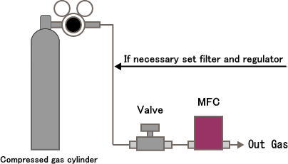
Schematic Diagram Of The Gas Mixer Examined Mfc Mass Flow Controller Download Scientific Diagram

P Id Symbols Complete List Pdf Projectmaterials
P Id Symbols Complete List Pdf Projectmaterials

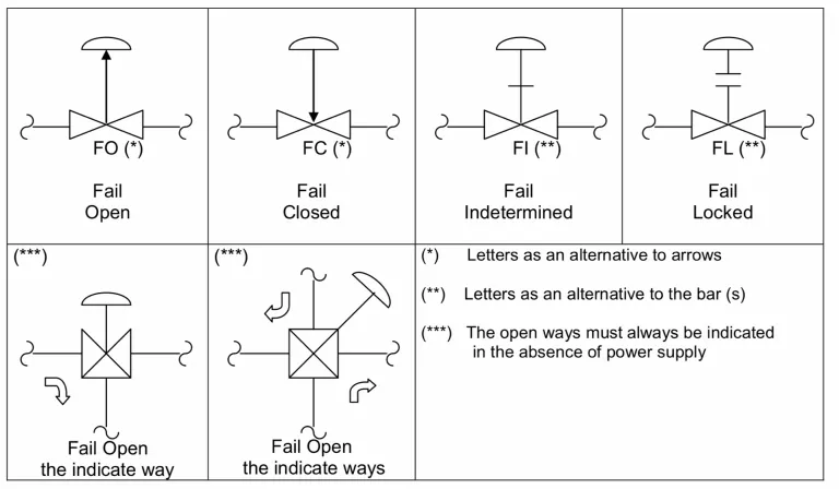
Datei Symbol Flow Control Valve Svg Wikipedia

Datei Symbol Flow Control Valve Svg Wikipedia
Mass Flow Controller C F Fcon Co Ltd
Kurt J Lesker Company Mks Gm100a Digital Mass Flow Controller Vacuum Science Is Our Business
P Id Symbols Complete List Pdf Projectmaterials

P Id Diagram Of The Laboratory Scale Sorption Apparatus G Gas Washing Download Scientific Diagram
P Id Symbols Complete List Pdf Projectmaterials

P Id Diagram Of The Laboratory Scale Sorption Apparatus G Gas Washing Download Scientific Diagram
![]()
Control Flow Diagram Png Images Pngwing

A Schematic Of The In Situ Volatile Hydrocarbon Gas Chromatographic Download Scientific Diagram

P Id Symbols Complete List Pdf Projectmaterials
How To Read Oil And Gas P Id Symbols Kimray

List Of Instrument Symbols In Pid Paktechpoint
P Id Symbols Complete List Pdf Projectmaterials
Mass Flow Controller C F Fcon Co Ltd